In this project i used arduino and XOR gate to power factor measurement.
What is power factor?
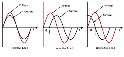
Power factor is a number between 0 and 1 refers to phase shift between voltage phase and current phase in AC appliances.
How to measure PF with Microcontroller (Arduino)?
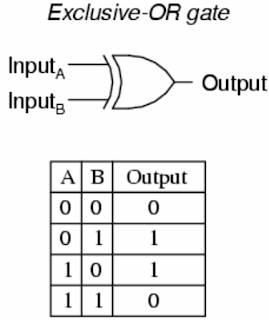
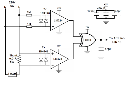
To measuring the power factor with microcontrollers, first of all we used Op-Amp to zero cross detection to find out the phase shift between current and voltage phase, the op-amp convert the sine wave signal comes from CT and PT with different amplitude to square wave with about 4v amplitude, then we connect these two square wave to XOR gate inputs.
XOR gate output will be 1 just when the inputs have different signals so when the load is resistive XOR gate output is 0 because both voltage and current phases start and ends in the same time, but when the load is inductive or capacitive XOR output is 1 because there are phase shaft between voltage and current,
Hence we can find the power factor by measuring the "ON-time" of XOR output, and put it in the power factor formula :
PF= COS(f*dt*360)
Where:
PF=Power Factor
f= Frequency (Hz)
dt=Time difference between two phases and/or XOR output ON-time (S)
Hence we can find the power factor by measuring the "ON-time" of XOR output, and put it in the power factor formula :
PF= COS(f*dt*360)
Where:
PF=Power Factor
f= Frequency (Hz)
dt=Time difference between two phases and/or XOR output ON-time (S)
Circuit:
Here we have two circuits, the first one using Current transformer(CT) and Voltage or potential transformer(PT), the only difference between them is that second circuit with no transformer and no insulation between microcontroller and main voltage so its dangerous if you touch any point in the circuit, but its cheap, small size, light weight and similar to commercial socket power meter.
Filtering capacitors between VCC and GND in this circuit is important to removing power supply noise( voltage ripple) to insure logic gate works well.
(Its better to connect a 100K resistor between non-inverting input of each Op-Amps and the ground).
XOR output signal when PF=1
(Its better to connect a 100K resistor between non-inverting input of each Op-Amps and the ground).
Arduino LCD wiring:
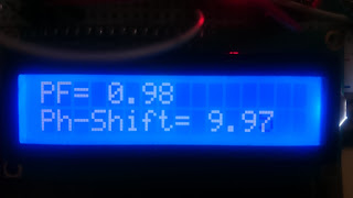
Results:
This picture shown voltage and current phases when PF=1
NOTES:
1-This project dealing with mains voltage so it is dangerous.
2-However transformers hasn't plus and minus, but the transformer dot convention is very important, because if CT and PT dot convention don't matching, the arduino will read low PF even with pure resistive load, So after making this project, first load you should connect to it is a pure resistive load such as incandescent lamp to make sure every thing is correct if the reading PF was much lower than 1 just flip over output wires of the PT transformer.
3-For current transformer you can use an Clamp-on transformer, I opened my old cheap clamp meter and used its transformer and works well.
In this video you can see how this project works:
Please subscribe to my YouTube channel here:
https://www.youtube.com/c/EngMousaalkaabi?sub_confirmation=1
3-For current transformer you can use an Clamp-on transformer, I opened my old cheap clamp meter and used its transformer and works well.
In this video you can see how this project works:
Please subscribe to my YouTube channel here:
https://www.youtube.com/c/EngMousaalkaabi?sub_confirmation=1
You can improve this project to power factor correction by adding some relays and capacitors and improving the code.
Parts list:
Arduino board https://goo.gl/XR3mXG
IC 4030 or IC 4070 (XOR gate)
Voltage Transformer 15V or less
Current transformer 5A/5mA
Resistor kit https://usa.banggood.com/custlink/DKKGszVu5t
Resistor kit https://usa.banggood.com/custlink/DKKGszVu5t
Resistor 100K
Resistor 220 ohm
Resistor 200 ohm
Potentiometer 10K or 100K (Potentiometer Kit https://goo.gl/z5b4X1)
Ceramic Capacitor kit https://goo.gl/q29Du3
Resistor 200 ohm
Potentiometer 10K or 100K (Potentiometer Kit https://goo.gl/z5b4X1)
Ceramic Capacitor kit https://goo.gl/q29Du3
LCD display 16x2 https://goo.gl/yTjFJS
Diode 1N4148 (4pcs) (Diode kit: https://goo.gl/zA6r7x)
LM324
Connecting wires https://goo.gl/BVC3pM
Breadboard https://goo.gl/rGuHzY
Energy meter: https://goo.gl/DztkwW
CODE:
#include <LiquidCrystal.h>
LiquidCrystal lcd(12, 11, 5, 4, 3, 2);
int pin = 13;
float rads = 57.29577951; // 1 radian = approx 57 deg.
float degree = 360;
float frequency = 50;
float nano = 1 * pow (10,-6); // Multiplication factor to convert nano seconds into seconds
// Define floats to contain calculations
float pf;
float angle;
float pf_max = 0;
float angle_max = 0;
int ctr;
void setup()
{
pinMode(pin, INPUT);
Serial.begin(9600);
lcd.begin(16, 2);
}
void loop()
{
for (ctr = 0; ctr <= 4; ctr++) // Perform 4 measurements then reset
{
// 1st line calculates the phase angle in degrees from differentiated time pulse
// Function COS uses radians not Degree's hence conversion made by dividing angle / 57.2958
angle = ((((pulseIn(pin, HIGH)) * nano)* degree)* frequency);
// pf = cos(angle / rads);
if (angle > angle_max) // Test if the angle is maximum angle
{
angle_max = angle; // If maximum record in variable "angle_max"
pf_max = cos(angle_max / rads); // Calc PF from "angle_max"
}
}
if (angle_max > 360) // If the calculation is higher than 360 do following...
{
angle_max = 0; // assign the 0 to "angle_max"
pf_max = 1; // Assign the Unity PF to "pf_max"
}
if (angle_max == 0) // If the calculation is higher than 360 do following...
{
angle_max = 0; // assign the 0 to "angle_max"
pf_max = 1; // Assign the Unity PF to "pf_max"
}
Serial.print(angle_max, 2); // Print the result
Serial.print(",");
Serial.println(pf_max, 2);
lcd.clear();
lcd.setCursor(0,0);
lcd.print("PF=");
lcd.setCursor(4,0);
lcd.print(pf_max);
lcd.print(" ");
lcd.setCursor(0,1);
lcd.print("Ph-Shift=");
lcd.setCursor(10,1);
lcd.print(angle_max);
lcd.print(" ");
//delay(500);
angle = 0; // Reset variables for next test
angle_max = 0;
}


