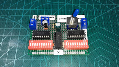
This circuit is a Frequency Divider and Frequency Multiplier by using IC 4017 and IC 4046 (PLL).
The output waveform will be square wave only (used for digital signals) and the max. output frequency is 1Mhz.
Parts list:
IC 4017 (2pcs)
IC 4046
Dip x10 switch (2pcs)
Toggle switch with 6 pins
IC Socket for 16pin IC (3pcs)
Resistor 470 ohm
Resistor 1.5K
Resistor 47K
Capacitor 100nF
Capacitor 100pF
Capacitor 220uF
Capacitor 2.2uF
Screw terminal 2P (3pcs)
Circuit:
Video:


